- Home
- Knowledge library
- The advantages of milk pre-cooling
The advantages of milk pre-cooling
How pre-cooling using a plate heat exchanger reduces electrical demand and speeds up final cooling.
Before using any form of mechanical cooling, it is advisable to pre-cool the milk, immediately on leaving the parlour. This reduces the electrical demand and speeds up final cooling.
Mains or borehole water can be used for pre-cooling by employing a Plate Heat Exchanger (PHE). Generally, mains or borehole water temperature is between 7-12°C, and if set up correctly it is possible to pre-cool the milk down to about 15°C. Cooling 1,000 litres of milk from 37°C to 15°C involves removing 25.5 of heat from the milk.
If a refrigeration cooler were used, operating at a Coefficient of Performance (COP) of 3.0, cooling to 15°C would require 8.5kWh (or 8.5 units) of electricity, costing £1 at a 12p/kWh daytime tariff; this is therefore the amount that pre-cooling can save. For a dairy producing 6,000 litres per day, this potential saving amounts to £2,000 per year.
How to configure the Plate Heat Exchanger
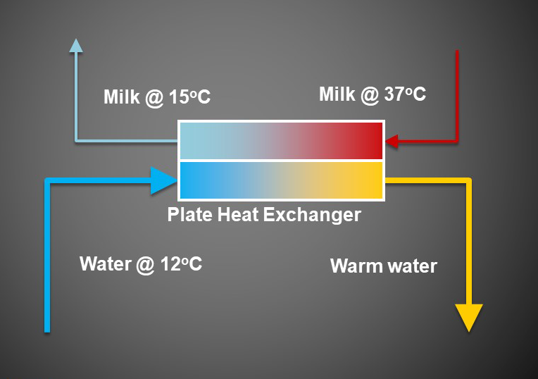
The quantity of pre-cooling achieved depends on the water/milk flow ratio and the surface areas within the cooler, so it is important to size the PHE and configure the flow rates and timing correctly to maximise heat transfer. Generally, a water/milk flow ratio of 2:1 is optimal and contributes 40-60% of the cooling duty. Crossflow exchange (where coolest water enters where the milk exits, thereby achieving the best cooling potential) is necessary to ensure that cool milk leaves the PHE at the same end as cool water enters, so reversing the connections must be avoided.
Water warmed by pre-cooling should be stored and used to minimise waste, for example in cattle drinkers, or for washing. Water use can be minimised by using a controllable valve which allows water to flow when the milk pump is running, and closes a preset time after the milk pump stops. Various studies have shown that 10-20 seconds water flow post milk pump stop will ensure the PHE is ready for the next flow of milk.
Figure 2 shows the correct configuration of flow rates and directions to achieve the temperatures suggested.

Figure 2: Plate heat exchanger - configuration of flow rates and directions.

